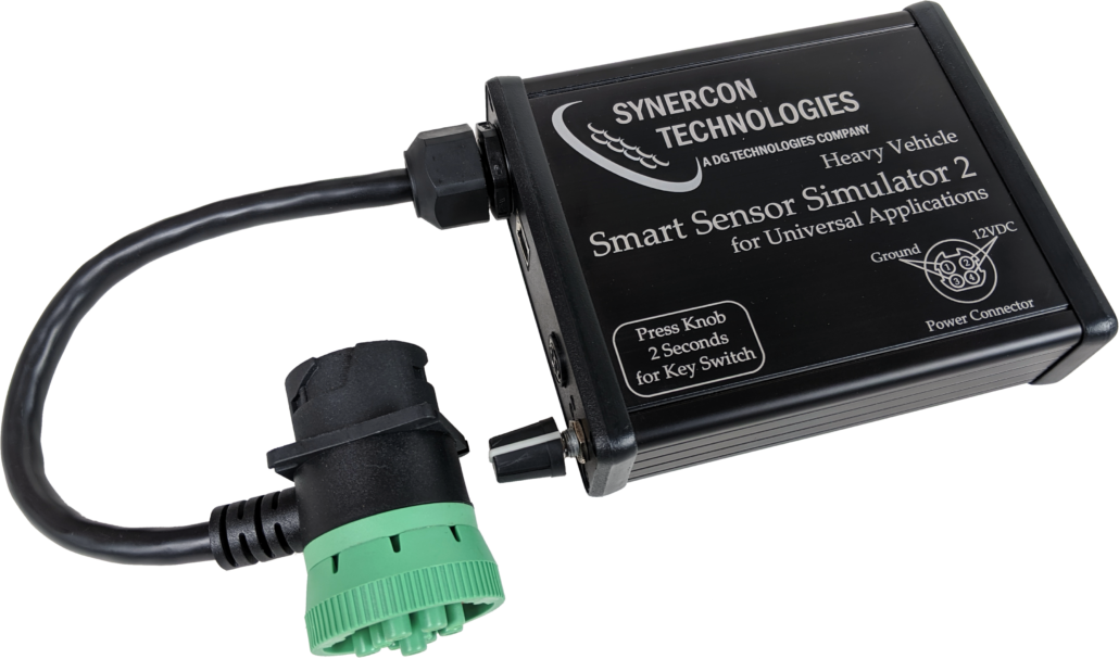
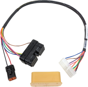
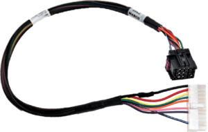
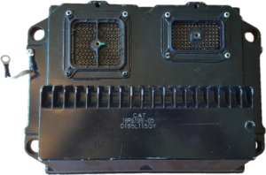
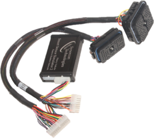
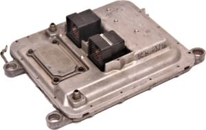
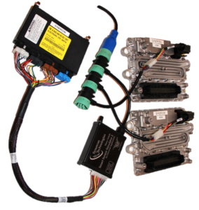
The Smart Sensor Simulator 2 is a small device to simulate a big truck

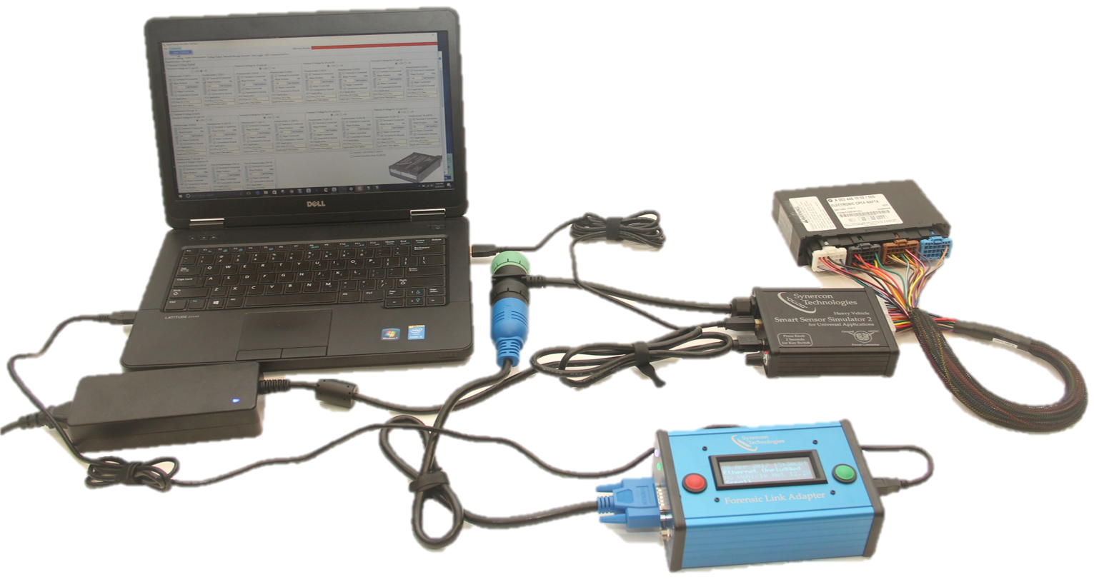
The Smart Sensor Simulator 2 is a universally compatible device that emulates the electronic systems of a truck. This “truck-in-a-box” technology enables investigators to retrieve data out of electronic control units (ECUs) from damaged vehicles and perform a forensically sound bench-top download. You can use any RP1210 device to connect to the SSS2 through its built-in 9-pin connector. You can also use the Forensic Link Adapter to perform a benchtop download with the SSS2. The SSS2 is adjustable by the user with our Smart Sensor Simulator Interface program so a single SSS2 can provide solutions across the wide array of ECUs found on the road.

Smart Sensor Simulator 2 (SSS2)

The Smart Sensor Simulator 2 provides a necessary connection between any vehicle diagnostics adapter (VDA) and an electronic control unit (ECU).

User Panel of the SSS2

1
2
3
4
5
6
1

Male/Female Deutsch 9-pin connector

2

USB interface cable to communicate with a PC

3

+12VDC IN

4

Power Indicator. If J1939 network traffic is present, this LED will flicker at a rate reflecting the J1939 busload

5

Key Switch Indicator. If J1708 or CAN traffic is present, this LED will flicker

6

User Input Knob. Press knob for 2 seconds to cycle the key switch relay.

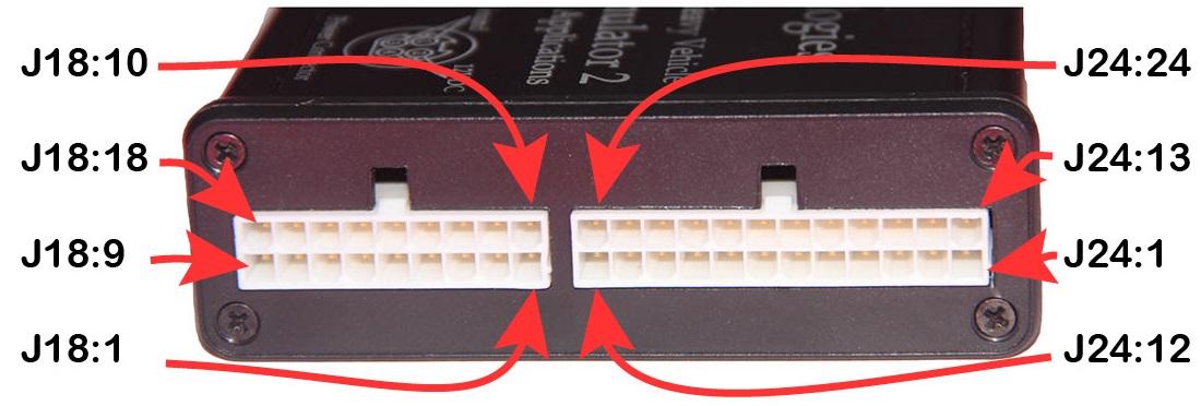
SSS2 Pinout Information

The white Molex Mini-Fit Jr. connectors on the end of the SSS2 provide a modular solution for interfacing with different SSS2 wiring harnesses. For pinout specifications, click below:

  1. Digital Potentiometer (10k) or PWM5*
  2. Digital Potentiometer (10k) or PWM6*
  3. Digital Potentiometer (10k) or CAN1L*
  4. Digital Potentiometer (10k) or CAN1H*
  5. Digital Potentiometer (10k)
  6. Digital Potentiometer (100k)
  7. Digital Potentiometer (100k)
  8. Digital Potentiometer (100k)
  9. Digital Potentiometer (10k)
  10. Digital Potentiometer (100k) or Analog Out – B
  11. Digital Potentiometer (10k) or +12V Output
  12. Digital Potentiometer (100k) or Ground Output
  13. Digital Potentiometer (10k) or PWM1
  14. Digital Potentiometer (100k) or PWM2
  15. Digital Potentiometer (10k) or Analog Out – A*
  16. Digital Potentiometer (100k) or LIN
  17. CAN2L or J1708-
  18. CAN2H or J1708+
  19. High Current Regulator Adjustable Output
  20. Ignition Switch (+12V Relay)
  21. J1939L
  22. J1939H
  23. +12V Output (protected)
  24. Ground

*Only on hardware revision 5 and up.

  1. Ground Out or PWM4
  2. Analog Out – A
  3. Analog Out – B
  4. Analog Out – C
  5. Analog Out – D
  6. Analog Out – E
  7. Analog Out – F
  8. Analog Out – G
  9. Analog Out – H
  10. +12V Output or PWM3
  11. High Current Regulator Adjustable Output
  12. Digital Potentiometer or PWM4*
  13. Digital Potentiometer
  14. Digital Potentiometer
  15. CAN2L or PWM1
  16. CAN2H or PWM2
  17. Battery + Input (unprotected)
  18. Ground

*Only on hardware revision 5 and up.

SSS2 Passive Resistor Network

Some ECUs have more pins than the Smart Sensor Simulator 2 can accommodate. To remedy this, we have a Passive Resistor Network that provides simple fixed resistances to emulate connectivity to devices like coil solenoids. This gives an ECU the sense that those actuators are connected, thus eliminating the fault codes associated with missing connections. Schematics for the Passive Resistor Network.pdf

Check out the Smart Sensor Simulator 2 Overview 2017.pdf presentation for visual descriptions and details.

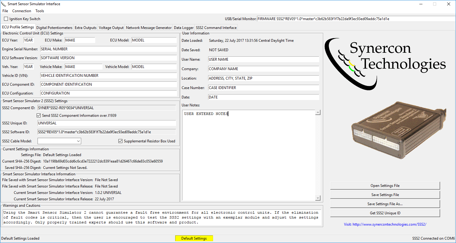
Smart Sensor Simulator Interface

A Graphical User Interface (GUI) to set configurations for the SSS2 to accommodate different ECUs for the entire fleet.

Current Release – v1.0.8

The installer includes a serial driver to communicate with SSS2 from Windows 7 and 8. Windows 10 should already have the driver installed. You may need administrator privileges.

Settings Files

The latest set of SSS2 settings files come bundled with the executable. They are also available as a .zip file.

For some cables there will be multiple files. These files were produced for individual ECMs and may not be appropriate for all control modules. Even if ECMs look alike, the programming on the inside may be different. This means using these cables and the SSS2 may still produce fault codes on the ECM. The settings file and the SSS2 should be tested on an exemplar unit before performing a forensic download.

See Release Notes for previous releases, bug fixes, and new features.

Click here for additional information on using the Interface Application.

Definitions and Capabilities:

CAN – Controller Area Network up to 1M bits/sec

LIN – Local Interconnect Network. This is programmed to simulate the shifter lever on Freightliners with an automated transmission.

PWM – Pulse Width Modulated with adjustable frequency and duty cycle. These are 0 to 5V square wave signals.

Digital Potentiometers

The digital potentiometers are 12V tolerant devices with independent terminal connection control. A potentiometer has three terminals: Terminal A, the Wiper, and Terminal B connected to ground. The potentiometer is rated to have a resistance from Terminal A to Terminal B. The wiper picks off from along the resistor string. The terminals can be configured to open and close independently. This gives you the ability to connect the potentiometer as a voltage divider, resistance to ground, or resistance to a high source. The terminals are connected by selecting the checkboxes on the SSS Interface under the Digital Potentiometers tab.

Digital potentiometers can simulate signals that are used for

  • Temperature Sensors
  • Pressure Sensors
  • Analog Accelerator Pedals
  • Actuator Presence (i.e. the presence of an actuator)

The digital potentiometers used in the SSS2 are the MCP41HV51  and MCP45HV51. The digital potentiometers have a limit such that the wiper plus the terminal is between 250 to 300 ohms.

Analog Output

Analog outputs generate signals from 0 to 5 V. The signal is generated by a Digital to Analog Converter (TI DAC7678) and buffered with an op-amp. Each signal is capable of sourcing 25 mA. 

Analog Outputs can simulate signals for:

  • Pressure Sensors
  • Switches to ground (by setting the output voltage to 0)

Analog outputs are similar to a voltage divider when examining the signal with a meter. However, voltage dividers based on a potentiometer sink current and analog outputs can both sink and source current.

Pulse Width Modulated Output

Pulse width modulated outputs are square waves from zero to +5V that have an adjustable frequency and duty cycle. These signals can be used to simulate analog values by adjusting the duty cycle. In other words, a voltmeter will read between 0 and 5v based on the duty cycle. A duty cycle of 0 means the output is driven to ground through an op-amp. A 100% duty cycle means the signal is always on at +5v. The frequency can be set from 0 to 5000 Hz. 

Pulse width modulated signals are the only way to simulate throttle position sensors for some ECUs, like Caterpillar and PACCAR MX.

These signals can also be used to generate speed signals for researching event data recorder capabilities.

Not all channels have independent frequency settings. The PWM1 and PWM2 signals have a common frequency that can only go as low as 245 Hz. PWM3 and PWM4 share the same frequency. PWM5 and PWM6 share the same frequency. The output of PWM 3 shares the pinout for a swithed +12V supply and has a 10uF capacitor to ground. This capacitor acts like a low-pass filter, so high frequency values on PWM3 tend to be averaged out and do not show the switching behavior of the other PWM signals.

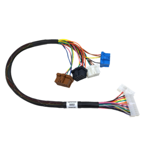
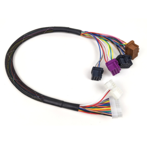
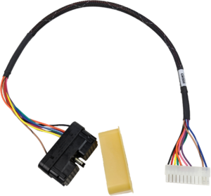
SSS2 Cable Harnesses and ECM Examples

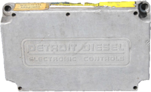
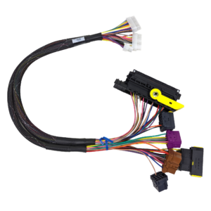
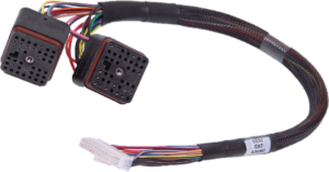
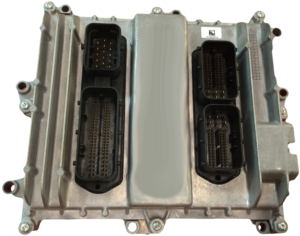
Detroit Diesel DDEC 10/13

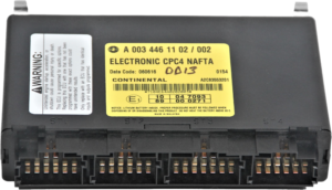
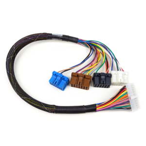
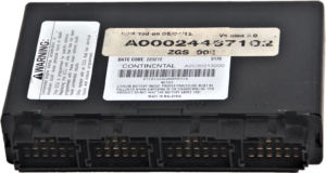
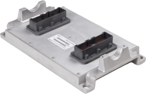
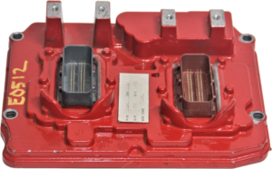
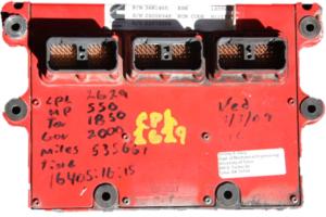
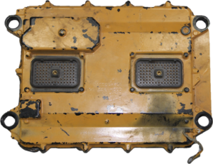
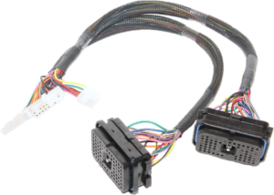
The Common Powertrain Controller (CPC) from Detroit Diesel engines found in many Freightliner trucks houses the DDEC Reports data. This cable interfaces with the CPC only and provides a simulated connection to the other DDEC modules. This cable fits CPC2 and CPC4 modules for years 2010 and newer. The configurations on CPCs can vary, so you mus choose the most appropriate settings file for your application.
Detroit Diesel DDEC VI

The DDEC6 CPC is used in conjunction with a Motor Control Module to control the EPA07 compliant Detroit Diesel Engine run. This CPC unit contains the DDEC Reports data, but does not track diagnostic events. The DDEC 6 was used from 2006-2009 (approximated).

Mercedes Benz Engines

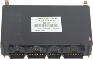
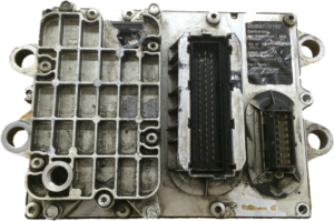
The vehicle control unit (VCU) contains the Data Pages accessible by DDEC Reports. The settings file contains the information needed to simulate a connection to the PLD for a fault free download, so long as the settings are applied. The MBE PT-CAN messages are at 125 kbaud.

Detroit Diesel DDEC V

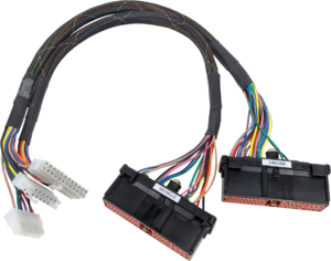
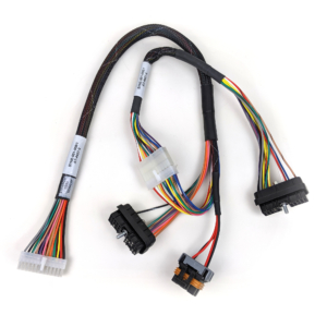
The DDEC Reports software can extract Data Pages from this module over the J1708 network. This cable is designed to enable fault free conditions so long as the correct SSS2 settings are applied. There is an extra connector to house wires that are not use with the SSS2.

Detroit Diesel DDEC IV

The DDEC Reports software can extract Data Pages from this module over the J1708 network. This cable is designed to enable fault free conditions so long as the correct SSS2 settings are applied. This is a 2-part cable.

Mercedes PLD and VCU

This cable system has both connectors for the Vehicle Control Unit and the PLD, which is engine mounted. The VCU is mounted in the cab and predates the DDEC CPC. The PLD has configuration and fault data that can be accessed using the DDDL software. The VCU has Data Pages that can be accessed with DDEC Reports.

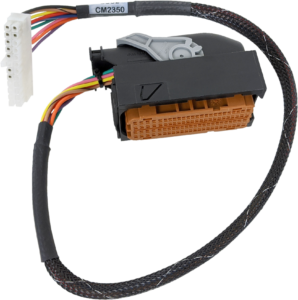
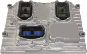
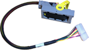
Cummins CM2350/2450

This is a communications-only cable for the Cummins CM2350 and CM2450 found on most newer Cummins engines. This works with the default settings. Communications only cables will still set fault codes.

Cummins CM2250

This is a communications only cable and has both power and communications in one 60-pin Deutsch connector.

Cummins CM2150

This is the CM2100 series module that can communicate with Cummins CM2150 modules. It has a 60 pin Deutsch connector for communications and a 4 pin connector for power.

Cummins CM800 Series

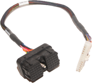
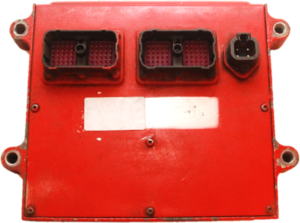
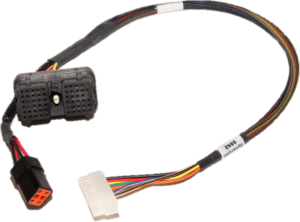
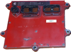
The CM800 Series cables are enabled with the default file settings. These are communications cables only and will set new fault codes. They use the Deutsch 40 pin connector with  Key #4. These cables will connect to the Cummins CM850, CM870, CM871, and the CM875.

A custom CM870 cable with both connectors for full engine simulation is a special order item.

Cummins CM500 Series

The CM500 Series cables are enabled with the default file settings. These are communications cables only and will set new fault codes. They use the Deutsch 40 pin connector with  Key #1.

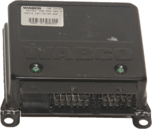
Wabco Brake Controller

This cable establishes communications only for the Wabco brake controllers. The Wabco Toolbox software can be used to communicate with the module.

Caterpillar ADEM4

The ADEM4 module has more input wires than there are cavities for the SSS2. Therefore, an additional resistor box is included for this cable to simulate some sensors using resistors. This is the only cable that needs the resistor box at this time.

Caterpillar ADEM 3 or ADEM 2000

There is an extra set of wires that are not use on this cable. Those wires exist on the schematic, but do not generate fault codes. There is an extra connector that does not plug into the SSS2. This extra connector has circuits that are not used to set a fault free environment.

Caterpillar ADEM2

The ADEM2 will likely not have snapshot data.

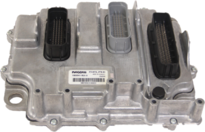
PACCAR MX

This cable works with the default settings. This is for communications, power, and ignition only. Using this cable will produce new fault codes.

Navistar MaxxForce

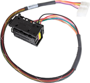
This cable works with the default settings. This is for communications, power, and ignition only. Using this cable will produce new fault codes.

Bendix In-Cab

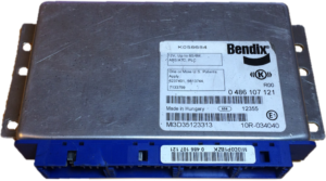
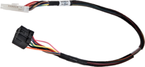
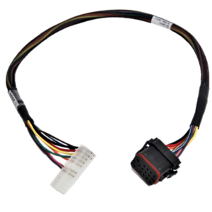
The Bendix In-Cab Settings is setup for a cable has a 17 pin connector on it that has a special key so the truck can detect if the cable is unplugged from the ECU. It also powers on the Bendix Controller with a lower voltage (around 8 volts), which keeps the controller from overwriting any existing fault codes. This cable will work on the EC-60 and EC-80 series controllers.

DDEC 10/13 MCM and ACM

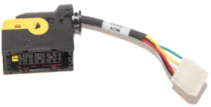
The Detroit Diesel Motor Control Module and Aftertreatment Control Module have the same shape. They do not store any event data, just fault codes and configuration information. They are accessed by attaching the 21-pin cable adapter to the 9-pin extension. This creates network connections on the power train CAN for the modules. This is for communications only, so fault codes will be set due to the lack of the 120 pin connector. It is recommended to examine the CPC by itself first to keep fault codes to a minimum. Once the CPC is downloaded, then connect the MCM, ACM. The CPC is required to communicate with the MCM and ACM. See Smart Sensor Simulator 2 Protocol for MCM and ACM for more information.

Bendix Chassis

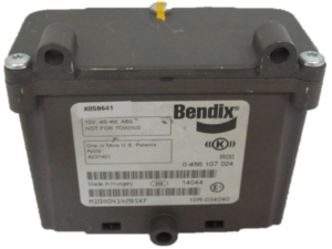
This cable enables communications for a Bendix EC-60 chassis mounted brake controller.

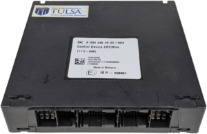
CPC3 Evo

The CPC3 Evo will communicate only under specific conditions. You will need to change the baud rate of your SSS2 and enable communications in the SSS2 Interface Application. You may need to activate your module using DiagnosticLink™ before it will communicate. The FLA can not download reports from CPC3 modules as the FLA was not designed to support 500k CAN, however other VDAs such as the DPA5 Pro can be used. Detailed instructions can be found on the CPC3 Evo product page. 

The Smart Sensor Simulator 2 is an open design developed by Dr. Jeremy Daily, Associate Professor of Mechanical Engineering at the University of Tulsa. The details of the system including the circuit schematics and firmware are available on his Github repository.